Electronics Project: Bicycle Lights
Here are my designs for front & rear bicycle lights. I made the rear light first (April 2021), the front light followed later (March 2022) so it has a different design.
Both lights were born out of frustration with existing bicycle lights. I have yet to see a store-bought light handle a low battery gracefully. And often enough they either are removable, but often turn on in your jacket pocket, so the battery dies, or fixed, and corrode away because they stay moist on the inside because I have to park my bike outside.
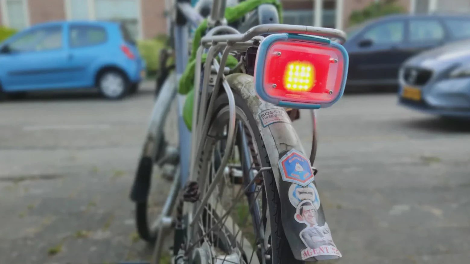
To solve this, mine are housed in simple food storage boxes that attach to your bike with velcro. That way you can bring them indoors & open them up after biking through the rain, letting them dry on all sides.
Both the front & rear light are driven by an 18650 battery that lasts for months. They periodically measure the battery level, and when it’s getting low, they turn off half the LEDs. That way you can see that it’s time to recharge, but you still have some illumination.
Rear Light
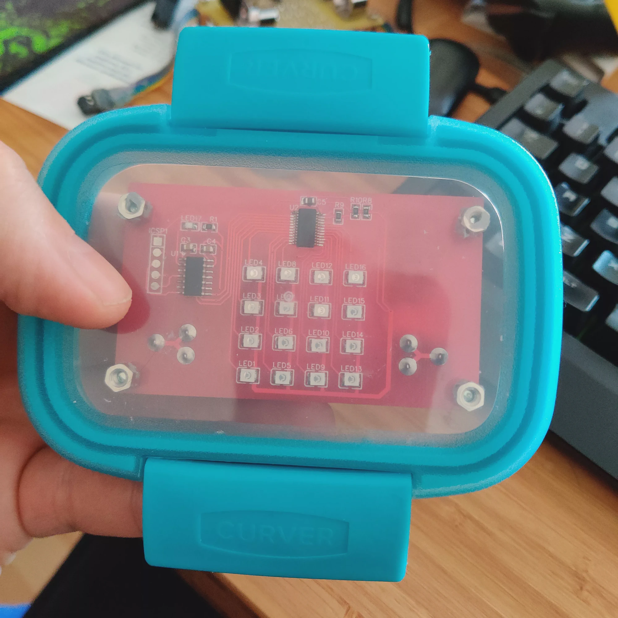
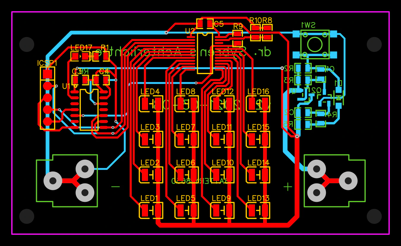
The main components of the rear light are:
- ATtiny84 microcontroller.
- 16x red LEDs (3528 SMD).
- TLC59283DBQ LED driver IC.
- 18650 Li-Ion battery.
- Latching circuitry with a single power toggle button.
Source code for the ATtiny84 can be found on Gitlab: dr.sybren/attiny84/fietslamp.
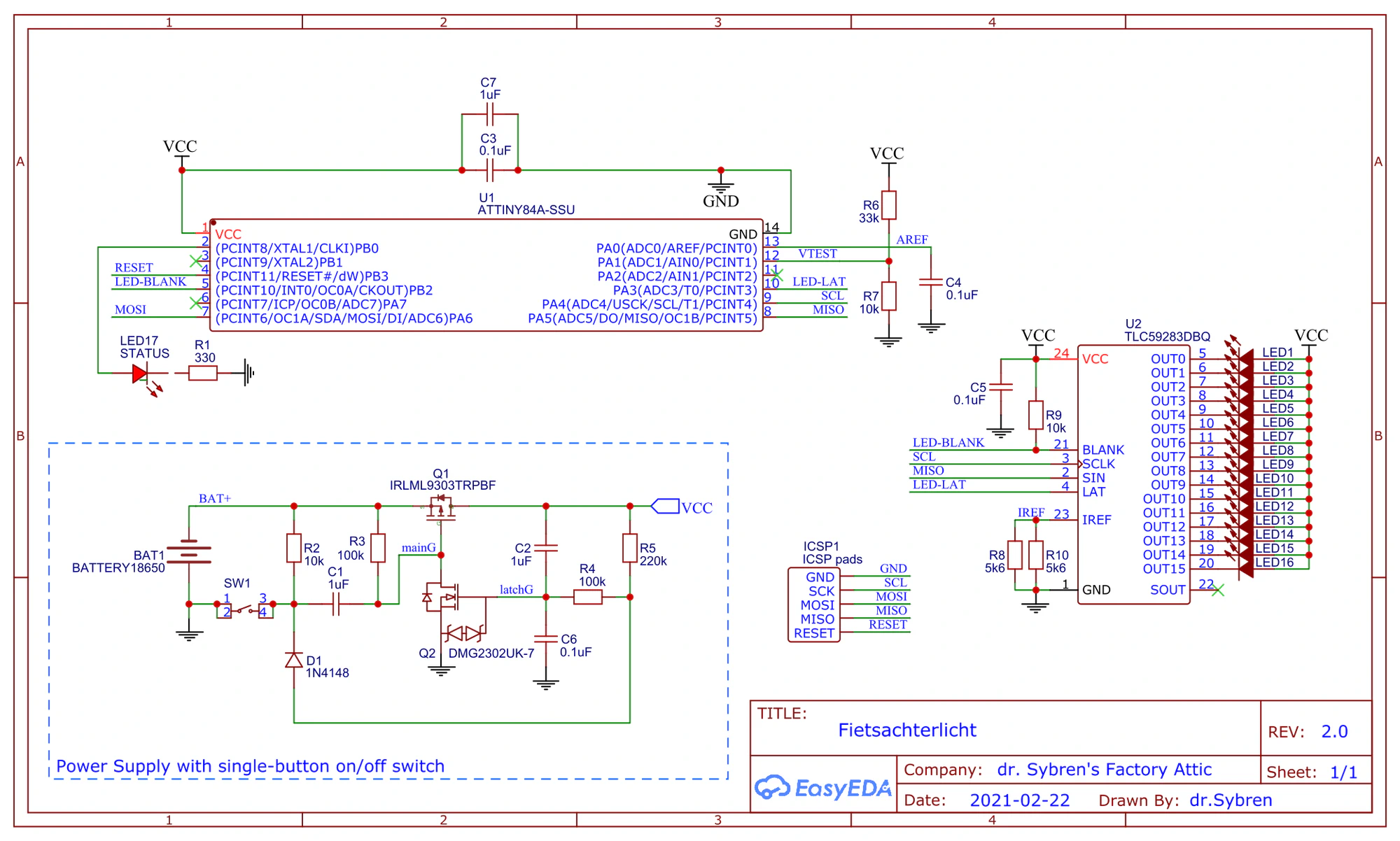
Battery Measurement
The microcontroller uses a voltage divider to measure VCC via an analogue input. This is measured at startup, and shown as a “progress bar” on the outer LEDs.
This initial measurement is done multiple times, and the result is heavily averaged in software. Effectively the “progress bar” slowly grows until it hits the final value, which is then shown for around 2 seconds.
The slow buildup removes oscillations. Since the battery voltage will drop a bit when the load increases, showing all LEDs at once (because the voltage is high) will drop the voltage, causing less LEDs to show, which lowers the current draw on the battery, making the voltage rise again, causing more LEDs to light up, etc.
LED Patterns
Of course the nerd in me wanted to have really nice flashy light patterns that show off what cool things you can do with a 4x4 LED matrix. Traffic safety is more important, though, so now it just shows a very subtle breathing pattern, but is solid red most of the time.
Every few seconds the battery voltage is measured. If it’s too low, half the LEDs turn off to show a checker pattern.
Power Management
The hardest part to design was the latching circuitry. I wanted the battery to last as long as possible, and thus to have the ICs really turned off when the light is out. This also made programming the microcontroller fairly easy, as it only has to start up and run until it looses power.
Front Light
The main components of the front light are:
- ATtiny85 microcontroller.
- 8x white LEDs (SMD, not sure which package).
- PCA9624PW LED driver IC. This is a simpler one than for the rear light, as it only needs to drive 8 LEDs.
- 18650 Li-Ion battery.
- 3.3v linear regulator with shutdown pin (MCP1826T).
- Tacticle button ( C&K PTS525).
Source code for the ATtiny85 can be found on Gitlab: dr.sybren/attiny85/fietslamp-koplamp.
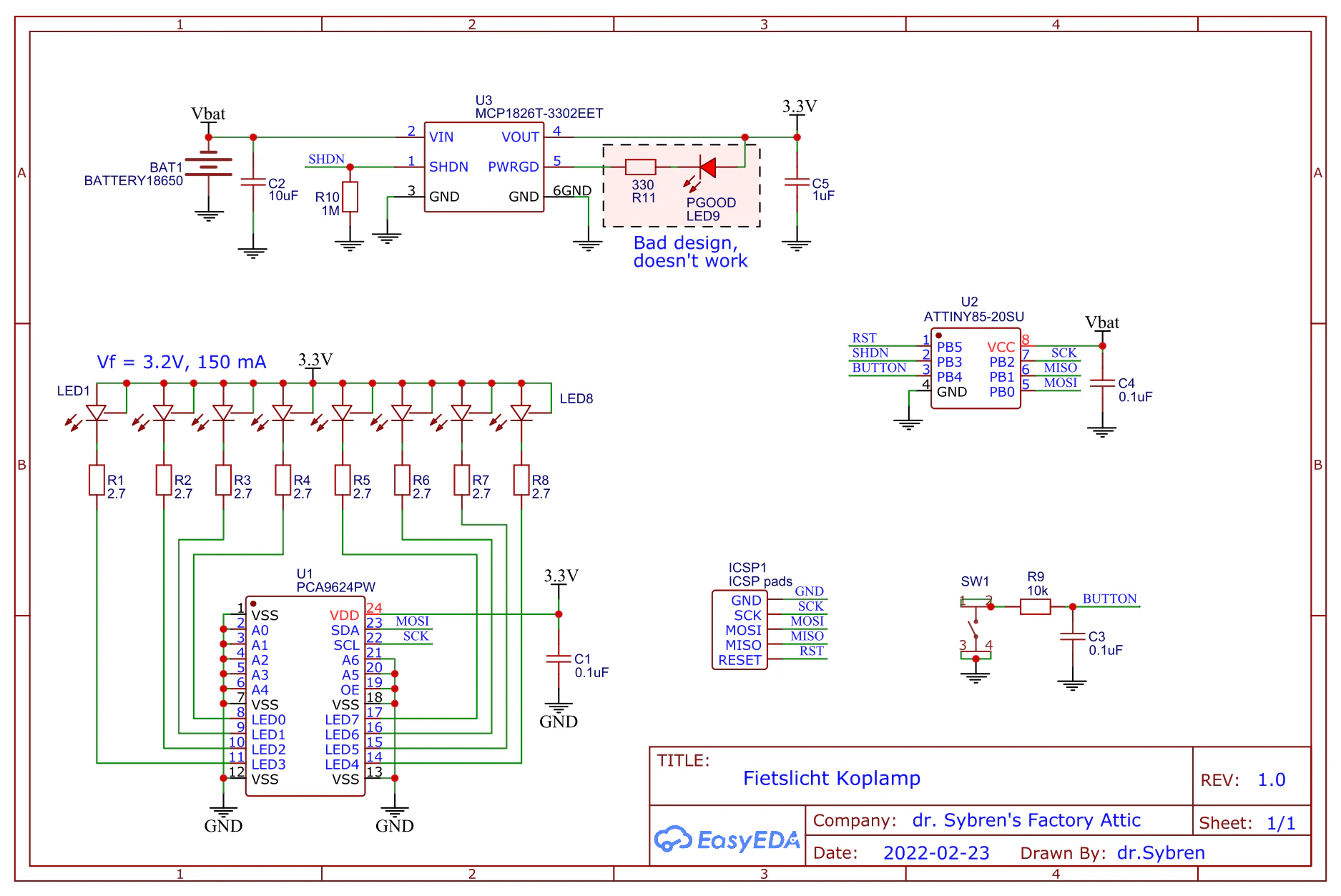
Battery Measurement
Contrary to the rear light, this one uses a different technique for measuring the battery voltage. This trick uses an internal, fixed 1.1v reference voltage. You can tell the ATtiny85 to measure this 1.1v, and to use its VCC as the maximum value that can be measured. Since you know that it’s always measuring 1.1v, and that measuring VCC will produce a readout of 1023 (the maximum value of its 10-bit ADC), the read value can be used to compute VCC.
As far as I know this works with all the ATtinies and ATmegas. And you don’t need to sacrifice an I/O pin to do the measurement, which was kind of vital because of the low pin count of my beloved ATtiny85.
Power Management
The front light is basically an improvement over the rear light. It was an experiment to see how realistic my desire was to have everything really turned off when the lights are out. So, instead of external power switch circuitry, I just let the microcontroller sleep. Also I gave it control over the 3.3v regulator that powers the LEDs and the LED controller. That way it could still completely disable that part of the circuit.
As it turned out, an ATtiny85 in deep sleep hardly uses any current. Battery life is still incredible, I don’t remember ever charging the battery since I started using it almost two years ago.
Button Debouncing
A short press of the button wakes up the microcontroller. Holding it will send it back to sleep again. I used a 10k resistor and a 0,1µF capacitor as a debouncing filter. Whenever possible I like to debounce my buttons in hardware. Microcontroller programming is hard enough, and I don’t want to think about bouncing buttons while I’m doing that.
LED Patterns
When the microcontroller is awake, a short press of the button will switch between solid light and a Knight Rider pattern. Of course I used an episode of Knight Rider as reference to get the timing right!
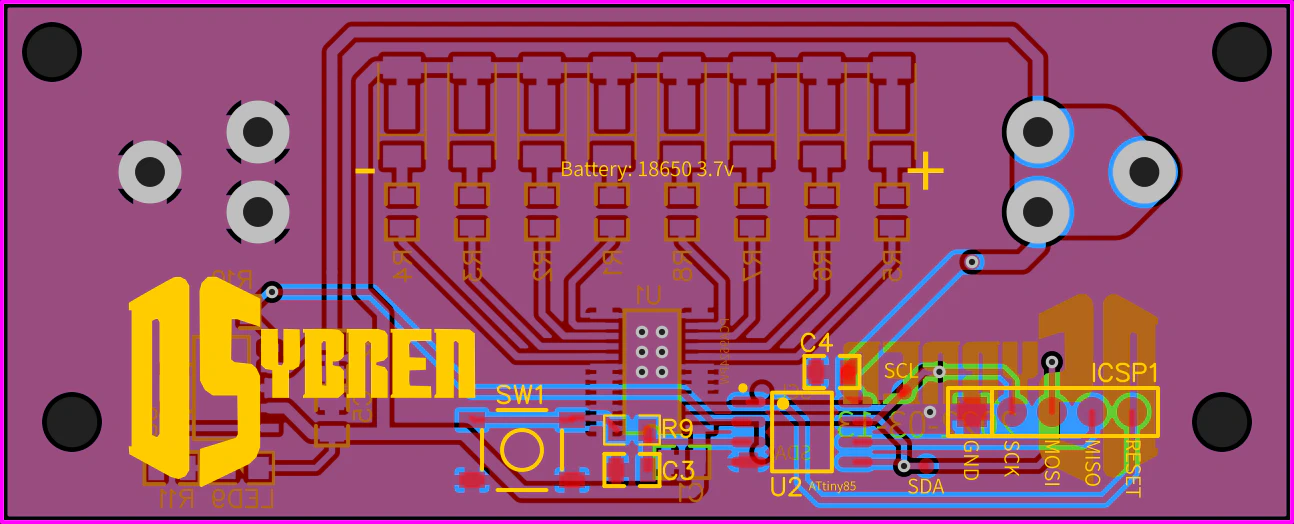
PCB Fabrication
For these projects, I decided to get the PCBs factory made. Usually I make them myself, but then they don’t have a protective solder mask. These things are meant to be used outdoors, and so I figured they could use all the protection they could get. The PCBs were designed with EasyEDA, and made by JLCPCB (the company running EasyEDA).